
Portable Earthing Introduction
Product Enquiry
Description
Portable Earthing and short-circuiting equipment is temporarily installed on isolated power circuits to provide a controlled path for short-circuit current. The equipment is essentially for worker safety and has been tested at a NATA accredited lab.
TMAC has been designing and developing portable earthing and short-circuiting equipment for more than 25 years. We offer an extensive range of reliable equipment, adaptable to numerous types of installations.
- Earthing and short-circuiting devices for fault currents from 8.6 kA to 31.5 kA – 0.5 s
- Copper cables 25 mm², 35 mm², 50 mm², 70 mm², 95 mm²
- Aluminium cables 50 mm², 70 mm² 95 mm² and 150 mm²
- Wide variety of clamps suitable for a wide range of connection points and common types of applicator tools
In addition we are able to cater for customers’ specific needs and provide:
- Technical advice
- Design and development of equipment
- Refurbishment and routine inspections
Portable Earthing Maintenance
Every TMAC portable earthing device must be handled and stored with care to ensure it remains capable of achieving its full rating during its service life. Maintenance includes periodic visual inspection of all components, cleaning of conductor clamps, cables and insulating sticks. Although the connections are engineered for a long service life, particular care should be taken to ensure that strands are not broken in the vicinity of the cable lugs. TMAC has a comprehensive maintenance user instructions that is available at the resources/user instructions page. Click link here
Conformance
Users should be aware that application, use and maintenance of TMAC portable earthing and short-circuiting equipment may be regulated by government legislation or codes of practice.
Users should ensure that all applicable regulations and legislative requirements are complied with when selecting, using and maintaining TMAC portable earthing and short-circuiting equipment.
Parallel connection
Earthing and short-circuiting devices may be used in parallel to achieve a greater fault capacity.
The following conditions must be adhered to:
- Equal cable lengths and cross-sections
- Identical clamps and connection points
- 10 % de-rating factor of the total fault current
- Clamps directly next to each other
- Parallel rating = (number of sets) x (rating of 1 set) x (0.9)
Action in the event of a fault
If the portable earthing or short-circuiting device has been subjected to fault current, it should be removed from service immediately and disposed of.
For further information on selection, use and maintenance of portable earthing refer to IEC 61230:2008 Annex.C.
Portable Earthing Components
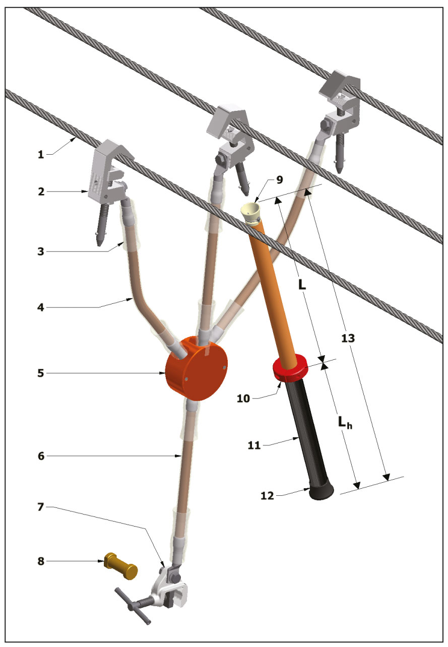
Components
- Phase Connection Point
- Phase Clamp
- Stress Relief
- Phase Cable
- Junction Point
- Earth Cable
- Earth Clamp
- Earth Connection Point
- Applicator Head (for removable stick)
- Optional Hand Guard
- Optional Handgrip over insulating stick
- Base Cap
- L – Insulating section, Lh – handle
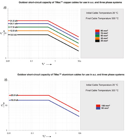
Fault Rating
Cable
The required cable cross-section depends on the rms short-circuit current (IR), the duration of the fault and the type of installation. The graphs below help to determine the required cable size for a given fault current (IR) and fault duration (sec).
Outdoor Use
For outdoor use the highest possible temperature rise is adopted to keep the weight to a minimum.
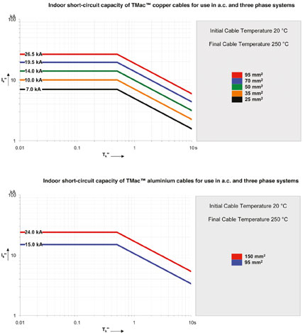
Indoor Use
For indoor use, the cable temperature is limited to a maximum temperature of 250 °C, to prevent gas emissions from the insulated covering, which may pose a risk to personnel.
Cable
Length
The length of the cables should correspond to the installation dimensions and distance between connection points.
Cables less than 1.2 times the distance between connection points may lead to more severe conditions than designed for. Cables more than 1.5 times the distance between connection points will cause unacceptable movement under fault conditions. Longer cables may be anchored by a non-conductive rope to reduce the movements.
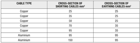
Reduction in size of earthing cable
Earthing cable cross-section in multi-phase sets may be reduced when used on a non-solidly earthed system.
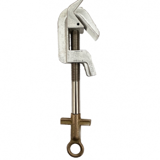
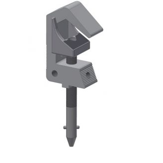
Portable Earthing Clamps
Clamps must be suited to the connection points that they are to be attached to. The table of standard clamps indicates their suitability click link here for PED Specification chart. In situations where a suitable clamp cannot be found, it is recommended that a fixed connection point is installed.
Related products
-
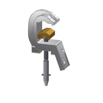
Type L Clamp 31.5kA / 0.5sec
Select options -

Portable Earthing Customer Selection Form and Specification Chart
-

Type B Clamp 25 & 33kA / 0.5sec
Select options -
Type A Clamp 17.5kA / 0.5sec
Select options -
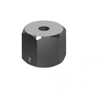
Type M Constant Pressure Nut 33kA / 0.5sec
-
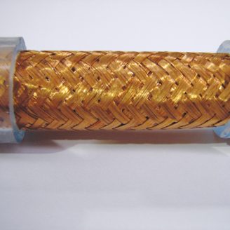
Copper Cables
Select options -
Type C Clamp 25kA / 0.5sec
Select options -

Type D Clamp 14kA / 0.5sec